
RS-485 interface and protocol: What is that ?
Uncategorized 11 May, 2015
RS485 interface/protocol
If we should to describe RS-485 protocol as short as possible it is simple serial communication protocol with 2 wires (4 wires for full-duplex) hardware interface, but powerful. Digital communications networks implementing the EIA-485 standard can be used effectively over long distances and in electrically noisy environments. Multiple receivers may be connected to such a network in a linear,multi-drop configuration. The standard has not defined a specific communications protocol. The standard UART (RS232) protocol is sometimes used. Most applications define a unique protocol.
As You can see below on the chart we may use this interface, when we need a long cable and/or when we need to connect devices in simple and cheap , but at the time save and stable industrial or home network.

Despite its widespread use, RS-485 is not as well understood as it should be. However, if you invest a little time on familiarizing yourself with the bus and pay attention to 10 aspects of your application, you'll find that designing rock-solid implementations is easy. Let me try to explain the RS485 interface and protocol.
The reason to use wired RS485 interface
Maybe a lot of you will be wondered why we are talking about RS485 interface. Why we should to use wired interface in the world where everything is wireless? There is very simple explanation of this question. Imagine that you have 3 points for monitoring and control your house. For example you have 2 temperature sensors and devices that can control temperature in two different rooms and possibilities to control your garage door. If you are using wireless network your home automation very easy can be put in unstable state or worst case the network can stop working. There are a lot of devices called "Jammer" devices. http://en.wikipedia.org/wiki/Radio_jamming.This is wireless signal blocking device used to block, blocks, jams or interferes with authorized wireless communications. These devices are cheap and can be bought from everywhere. Do you want to lose control on your devices ? That is the main reason to start to think about using wired networks. You will ask why exactly RS485 should to be used. Of course you can use ethernet embedded devices, but using this protocol you should to be very experienced at ethernet protocol and embedded microcontrollers. Second these devices are expensive. You should to understand LAN network and etc. If you are beginner it will very easy and cheap for you to build devices with RS485 interface.
Most significant features include:
- Only two bus lines are required + ground
- Simple master/slave comunication between all devices
Each device connected to the bus is software-addressable by a unique address - We can use UTP or FTP cable for comunication line.
- Simplicity and flexibility are key characteristics that make this bus attractive to many applications at home and industrial networks.
Hardware design - How to ...?
If we start for a first time to design RS485 network we need to know what hardware we should to use. There are a lot of companies on the market, but i prefer to use the SN75176 from Texas Instrument. http://www.ti.com/lit/ds/symlink/sn75176a.pdf. Looking at the picture below we can separate the chip of 2 parts.


On the right side we have external bus called 'A' and 'B' pins, where will be connected the 2 twisted wires. On the left side we see 4 pins. The chip SN75176 is transceiver and we have 2 pins we are using to send and receive information. Pin4 called 'D' is input and this pin should to be connected to the TX pin of the microcontroller( TX pin means line that will be used to send information over RS485 interface). Pin1 called 'R' is output of the RS485 chip and should to be connected to RX pin of the microcontroller (RX pin means line that will be use for receiving information in microcontroller from the RS485 interface). As you can see on the right picture above there are inside two devices in the chip - transmitter and receiver but they are connected just two wires ( pin 'A' and pin 'B'). Because this is transmitter and receiver at the same time we should to have possibilities to switch between this two modes. Pins DE and RE are used for this purpose. Below on the picture you can see schematic how to use SN75176 chip.

Because SN75176 is a transceiver (transmitter and receiver at the same time) we should to switch the chip between receiver and transmiter mode. We do this with pin RW and this pin should to be connected to an output of the used microcontroller. When this pin is logic '1' the SN75176 works as transmitter. If the state of this pin RW is logic '0' the chip is a receiver. Usually the RS485 network works in Master / Slave mode as soon as the last bit was transmitted over 485 interface the SN75176 should to be put in receiver mode. We will explain this detailed in the next paragraph. We can see on the picture above one slave device. In this example slave device just comunicate with master device. Master device can be PC or any embedded controller with RS485 interface. Let to take a look on the left side of the schematic. This is standart RS485 wiring of the SN75176. Jumper Line_T is used for line termination ( we will discuss this next paragraph ). Usually in the RS485 network there are two devices using switched "ON" line termination jumber: one in the beginning of the line and one in the end of the line. This jumper should to be switched "OFF" in the rest devices in the network. The resistors R3 and R4 are used to establise the fail save sircuit. The resistors R3 and R4 are used to establishes the fail save circuit. Schematic is taken from www.ti.com. Failsafe operation is a receiver's ability to assume a determined output state in the absence of an inut signal

485 network topology
When we are talking about RS-485 network we should to say that interface bus can be designed for Full-Duplex and Half-Duplex transmission. The RS-485 standarts sugests that its nodes be networked in daisy-chain. You can see below simple RS485 topology. It works but Texas Instrumets says that best is daisy-chain topology.
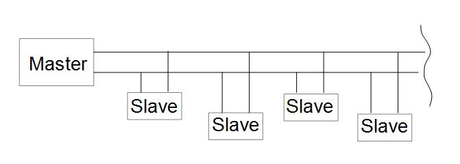
Best and avoided topology recommended from Texas Instruments of the RS485 device are shown below.

The last slave device should to have 120 ohm termination resistor. We can see on the Figure 2 the topology of the Full-Duplex and Half-Duplex RS485 network and we can see how it is terminated. The master is colored in red. Slave devices are green.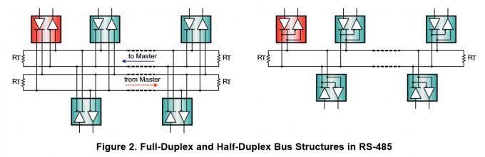
Full article for topology and hardware design of the RS485 device you can find on http://www.ti.com/lit/an/slla272b/slla272b.pdf
How many devices we can connect in this network ?
Because a driver's output depends on the current it must supply into a load, adding tranceivers and failsafe circuits to the bus increases the total load current requared. Standar-compliant drivers must be able to drive 32 of slave devices. Today's tranceivers often provide reduced unit loading, such as 1/8 unit load, thus allowing the connection of up to 256 transceivers on the bus.
Software: How to ?
Until now we talked about hardware design of the RS485 network. Let to talk about software that should to be writen and what we have to know about the communication between devices on RS-485 network.